
Pump Shaft Deflection: Why Seal Life Starts at the Bearing
What shaft deflection actually does to a mechanical seal, how the L3/D4 stiffness ratio predicts it, and what to ask a pump vendor before buying.
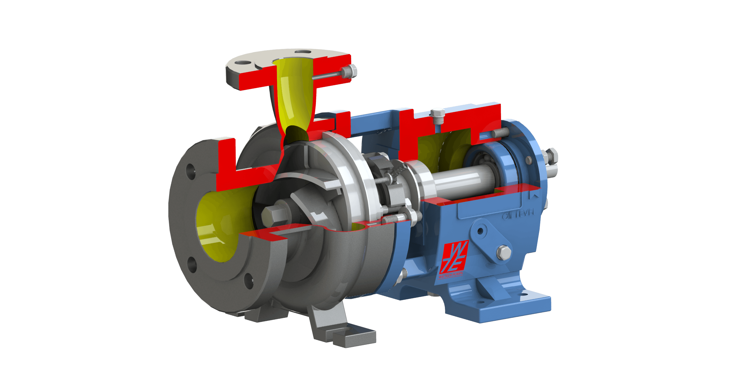
A mechanical seal is a precision flatness device running on a liquid film a few microns thick. It rarely fails because it is a bad seal. It fails because something moved. In an overhung centrifugal pump — the ANSI B73.1 configuration that dominates chemical, pharmaceutical, dye and effluent service — the thing that moves is the shaft, and how far it moves was fixed by geometry decided before the casing was ever cast. Pump shaft deflection is therefore not a maintenance variable. It is a purchasing decision. Plants that treat a repeat seal failure as a sealing problem replace the same consumable for years without ever touching the cause.
Why a seal cannot tolerate movement
Seal faces are lapped flat to a fraction of a wavelength of light and held together by spring load and hydraulic closing force. They work because the two faces stay parallel and concentric. The sealing literature puts the tolerance on displacement at the faces at roughly 0.001 to 0.002 in — about 25 to 50 microns. Past that, the faces stop tracking each other.
The important point is that shaft deflection is not a static offset. The radial load in a volute pump is fixed in space while the shaft rotates through it, so the faces open and close once per revolution. At 2,900 or 3,600 rpm that is a fatigue duty on the elastomers and a fretting duty on the drive components — which is why the failure presents as a worn O-ring or a fretted sleeve rather than as anything obviously to do with the bearing frame.
Field data supports this reading. In a two-year seal failure record compiled across two chemical plants, the single largest identified cause at both sites was inside- or outside-diameter rubbing of the rotating seal member against the stuffing box bore — 106 of 310 logged failures at the larger plant and 32 of 128 at the smaller. O-ring failure and bearing failure followed. Those are three different symptoms of one underlying condition: the rotating element is not staying where it was supposed to.
Where the radial load comes from
In a single-volute pump, the pressure distribution around the impeller periphery is only approximately uniform near the best efficiency point. The volute throat area is sized for one flow. At any other flow the velocity in the volute no longer matches the velocity leaving the impeller, the pressure recovery around the periphery becomes asymmetric, and the residual is an unbalanced radial force on the impeller.
The standard expression for that force is FR = KR × (H × s / 2.31) × D2 × b2, where KR is the radial thrust factor, H is head at the flow point in feet, s is specific gravity, D2 is impeller diameter and b2 is impeller width at the vane discharge including the shrouds. Two consequences follow directly from the form of the equation. Radial thrust scales with head, so a high-head stage carries a proportionally larger load. And it scales with vane width, which is why high-head wastewater and solids-handling impellers — wide by necessity, to pass solids — are structurally the worst case.
Why the load peaks at shutoff
The radial thrust factor reaches its minimum between roughly 80 and 100 percent of BEP flow, with the exact low point depending on specific speed and moving closer to BEP as Ns rises. Move left of BEP and it climbs quickly, reaching its maximum at shutoff — where head is highest and flow contributes nothing. Thrust intensity also increases with specific speed, so the same percentage excursion from BEP is not equally punishing across pump types.
The magnitudes involved are larger than most specifiers expect. A published worked example for a sewage pump with a manufacturer-approved operating range of 25 to 137 percent of BEP flow gives an unbalanced radial thrust of 522 psi at 40 percent of BEP against 59 psi at BEP — close to an eight-fold increase, inside the window the vendor printed on the curve. The approved operating range on a performance curve is a hydraulic statement. It is not a promise that the rotor was designed for the loads at its left-hand end.
The system decides where you actually operate
A pump does not run at its duty point. It runs where its curve crosses the system curve, and system curves drift. A gate valve gets replaced with a globe valve. A long horizontal run accumulates solids. A throttling valve is closed a little further each year to control an overflow. None of these are recorded as pump modifications, yet each moves the operating point left and raises the radial load. A rotor specified with no margin for that drift is a rotor that will be in the seal shop within a few years of commissioning.
From load to deflection: the cantilever
An overhung impeller is a cantilever. The deflection of a cantilevered beam under an end load is y = F × L³ / (3 × E × I), where F is the radial load, L the overhang, E the elastic modulus and I the second moment of area. For a circular shaft, I = π × D⁴ / 64. Substituting and collecting constants gives y ∝ L³ / D⁴ — the ratio the industry writes as L3/D4.
L is measured from the centreline of the radial bearing nearest the impeller to the impeller centreline; D is the shaft diameter under that bearing, taken nominally. The exponents are where the engineering lies. Because length enters cubed, trimming 10 percent off the overhang removes about 27 percent of the deflection. Because diameter enters to the fourth power, adding 10 percent to the shaft diameter removes about 32 percent. Nothing else available to the designer — material, bearing type, seal selection — has anything like that leverage. A stiffer steel buys a few percent; a bigger shaft buys a third.
For orientation: ANSI process pumps have historically shown L3/D4 values ranging from about 20 to 120, with newer designs reaching below 10. A commonly cited practical threshold is that a value below 60 markedly improves seal life under off-BEP operation. Above that, seal life becomes sensitive to exactly where on the curve the pump sits — which, as above, is not something the specifier fully controls.
Reading L3/D4 honestly
Two cautions. First, L3/D4 is a simplification. API 610 11th edition, Annex K, defines the full shaft flexibility index for a stepped shaft as ISF = L1³/D1⁴ + L1L2²/D2⁴, where L1 is the overhang, D1 the diameter under the seal sleeve, L2 the bearing span and D2 the diameter between bearings. In rotor proportions typical of process pumps the second term contributes only around 20 percent of the total, which is why the shortened form survives as shorthand — but it is shorthand, and a pump with an unusually long bearing span is exactly the case where the shorthand understates flexibility.
Second, a bare L3/D4 number is only comparable between pumps of similar size and duty. A pump making twice the head needs a stiffer shaft to hold the same deflection; so does one running at twice the speed. API 610 11th edition handles this with a size factor Kt = (Q × H) / N, evaluated at BEP with the maximum impeller rather than at the customer's duty, and a benchmark index fitted to service history: ISF = 32 × Kt^−0.76 in SI units. A vendor L3/D4 within 120 percent of that benchmark has historically not produced operational problems; above it, the standard asks for further consideration rather than outright rejection, weighing duty criticality, running hours, seal type and whether the real operating point sits well inside the design envelope.
What ANSI B73.1 guarantees, and what it does not
ASME B73.1 covers metallic and solid polymer centrifugal pumps of horizontal, end-suction, single-stage, centreline-discharge design. Its central purpose is dimensional interchangeability: pumps of the same standard dimension designation, from any source of supply, are intended to interchange with respect to mounting dimensions, size and location of suction and discharge nozzles, input shafts, baseplates and foundation bolt holes. That is a genuinely valuable guarantee. It means a plant can change vendor at replacement without repiping, and can hold one baseplate design across a mixed fleet.
But the guarantee is about the envelope, and rotor stiffness lives inside the envelope. Overhang length, shaft diameter under the bearing, bearing arrangement and seal chamber bore are not interchangeability dimensions. Two fully compliant B73.1 pumps that bolt to the same foundation can differ by a factor of several in L3/D4 — and therefore in how many seals they consume per year on the same duty.
Dimensional interchangeability guarantees that two ANSI pumps will bolt to the same baseplate. It guarantees nothing at all about how far their shafts move.
Note also the asymmetry in disclosure. API 610 11th edition requires the manufacturer to state the specific L3/D4 value on the datasheet where requested. B73.1 carries no equivalent obligation. On an ANSI purchase, the number exists but the buyer has to ask for it.
The design levers, and what each one costs
A stiffer rotor is not free, and understanding the trade-offs tells you which vendor claims are real engineering and which are marketing:
- Shaft diameter under the bearing — the fourth-power term, and by far the largest lever. The cost is a larger and more expensive seal, and loss of area at the impeller eye where the shaft is keyed, which can restrict flow and cost efficiency.
- Overhang length — the cubed term. Shortening it means a more compact bearing frame and tighter tolerance stack-up in manufacture.
- Bearing arrangement — double-row angular contact or paired thrust bearings raise load capacity and reduce the compliance at the support itself. The cost is a larger, heavier, more expensive drive assembly.
- Seal chamber geometry — a large-bore seal chamber in place of a narrow stuffing box does not reduce deflection, but it increases the clearance the rotating member has before it rubs, and improves flush circulation at the faces. Given that ID/OD rubbing is the leading recorded failure mode, this is a cheap and high-yield change.
- Impeller hydraulics — back vanes on an open impeller reduce the hydraulic load carried into the stuffing box and sealing region, attacking the load rather than the compliance.
- Suction geometry and NPSH margin — cavitation superimposes its own broadband dynamic load on the rotor. A shaft sized for steady radial thrust alone is being assessed against only part of its duty.
Using this at specification stage
Six questions that change the answer you get from a vendor:
- Ask for the L3/D4 value explicitly, and ask what it was computed at — the maximum impeller diameter, not your duty point, since the pump may be re-rated later.
- Calculate Kt = (Q × H) / N yourself from the published BEP at maximum impeller and compare the quoted value against 32 × Kt^−0.76. You need only the curve to do this.
- Ask for deflection at the seal faces across the intended operating range, not a single figure. A deflection number without an operating point attached is not a specification.
- Check the radial thrust at the left-hand end of the vendor's own approved operating window, and decide whether you would accept it.
- Specify the seal chamber and bearing protection alongside the seal. Lip seals on the bearing housing have a design life far shorter than the bearings they protect; contamination and water emulsion, not fatigue, is what usually kills a process pump bearing.
- Build a plant database. Tabulate L3/D4 against actual seal MTBF for your own fleet. Operating history is the final authority and it will sometimes contradict the ratio — the ratio is a good guide, not a verdict.
What a stiff rotor looks like in practice
To make the discussion concrete: AIRFIN's ACP Series is built to ANSI B73.1M and quotes shaft deflection below 0.05 mm at the seal faces, achieved through an oversized shaft carried on double-row thrust bearings, with a fully open impeller using back vanes to reduce hydraulic load on the stuffing box and sealing region, and IP66 bearing isolators on the housing. The series covers up to 350 m³/hr, 150 m head, 25.5 bar and −210 to 260 °C, at speeds to 3,600 rpm, with sealing options from gland packing to balanced cartridge double seals and a back-pull-out frame for maintenance without disturbing piping.
Read that figure the way you should read any vendor's: 0.05 mm is approximately 0.002 in, which sits at the upper edge of the displacement band the sealing literature treats as tolerable — comfortable for a seal, but a reminder that a deflection figure is only meaningful alongside the operating point it was computed at. That is the question to put to any supplier, including this one.
The practical judgement to carry away is this: seal life is a rotor design outcome, not a consumable quality outcome. If a pump is on its third seal in eighteen months, the useful diagnostic sequence is to establish where it is actually operating relative to BEP, calculate the radial thrust there, and ask the manufacturer for the shaft flexibility index — before specifying a more exotic seal face material. Upgrading the seal on a flexible rotor buys months. Correcting the operating point, or replacing the rotor with a stiffer one, buys years. AIRFIN manufactures the ACP Series in-house and can advise on shaft stiffness, seal chamber selection and retrofit options for existing installations.