
Tube Settler Design: Why 60 Degrees, and What It Costs
Why the surface area on a tube settler datasheet is not settling area, and how the 60-degree lay angle trades area for self-cleaning.
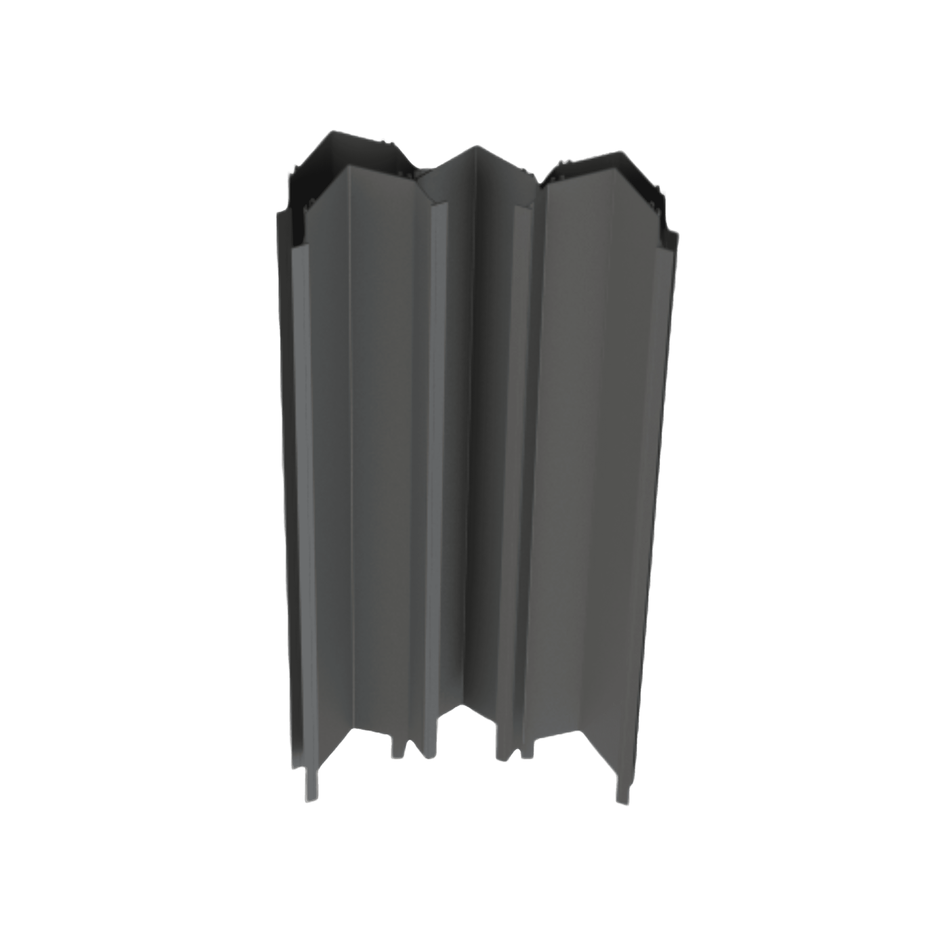
Every tube settler datasheet leads with a number in square metres per cubic metre, and every tube settler design that goes wrong goes wrong because somebody treated that number as settling area. It is not. It is a geometric property of the module, measured with the pack lying on a bench, and it takes no account of the fact that the pack will be installed on a slope. What clarifies water is the horizontal projection of that area, and at the industry-standard lay angle the projection is exactly half the headline figure. Miss the cosine and you commission a lamella pack that looks correct on paper, holds up through dry weather, and puts solids over the weir on the first hydraulic peak.
What a Surface Area Rating Actually Measures
Specific surface area is the wetted plate or channel-wall area contained in one cubic metre of media. It is honest, repeatable, and orientation-independent. AIRFIN's Chevron tube settler media is rated at 12 m2/m3 and the Square type at 14 m2/m3; the difference between them is cell geometry, not angle. The Chevron profile runs a 120 x 44 mm cross-section, the Square a 55 x 55 mm cell. The tighter cell packs more wall into the same volume, which is where the extra two square metres come from.
None of that is settling capacity. Sedimentation is governed by the area a falling particle can land on when projected onto the horizontal plane, because gravity acts vertically and the overflow rate you compare against is a vertical velocity. For an array of n inclined surfaces of width W and length L set at angle theta from the horizontal, the effective settling area is A_eff = n x W x L x cos(theta). The cosine is not a correction factor or a safety margin. It is the geometry.
The Cosine at 60 Degrees
Both AIRFIN media types are laid at 60 degrees from the horizontal, as is essentially all commercial tube settler media. Cos 60 degrees is exactly 0.5. A cubic metre of Chevron media presenting 12 m2 of wall presents 6 m2 of projected settling area; the Square type's 14 m2 projects to 7 m2. If you have sized a retrofit on the datasheet number, your clarifier has half the capacity you think it has. This is the single most common arithmetic error in lamella retrofit work, and it is silent — the tank still passes flow, it simply stops removing solids at roughly half the loading you expected.
The reason any of this is worth doing is the shallow-settling principle. In a conventional clarifier a particle must fall the full liquid depth to be captured. Inside a settler channel it must fall only the clear spacing between surfaces — a few tens of millimetres rather than several metres. Even after surrendering half the nominal area to the cosine, the reduction in settling path is worth far more than the area you gave up. Design guidance for upflow inclined plate and tube tanks puts the achievable surface loading rate at roughly 3 to 6 m3 per m2 per hour, about twice a conventional settling tank.
Why the Industry Converged on 60 Degrees
The angle has an odd history. The first observation that tilting a vessel accelerates settling belongs to the pathologist Arthur Boycott, who reported in a 1920 letter to Nature that red blood cells cleared faster in tilted tubes than upright ones — fastest, in his data, at about 56 degrees from the horizontal. His own explanation was wrong. Later workers (Ponder in 1925, Nakamura and Kuroda in 1937) identified the real mechanism: clarified fluid is released beneath the downward-facing upper wall and rises as a thin clear layer, so the suspension sheds clear liquid far faster than a vertical column can. That is the Boycott effect, and it underpins every inclined settler built since.
But the water industry did not arrive at 60 degrees by optimising removal. It arrived there by optimising sludge behaviour. Culp and co-workers, writing in 1968 as tube settlers were entering practice, put it plainly: an angle of 60 degrees provides continuous sludge removal while still allowing the tube to function as an efficient sedimentation device. The angle is a compromise, and the thing it protects is self-cleaning, not efficiency.
The Trade-Off, Stated Honestly
Steepening the pack cuts both ways. A steeper angle makes settled solids slide down the wall reliably into the sludge zone, and it lets you claim a higher nominal surface loading rate. It also shrinks the projected area as cos(theta), so for a fixed feed flow a steeper cell has less retention capacity and is more likely to carry particles to the overflow. The two effects pull in opposite directions, and the crossover is not at 60 degrees.
The experimental literature consistently finds the removal optimum below 60. Culp and colleagues and, later, Jimenez and Ramos found optimal angles for wastewater in the 35 to 45 degree band. Demir, working with bentonite and alum, found a best result near 50 degrees. High-resolution numerical simulation by Chang and co-workers found flow instabilities appearing below 45 degrees and identified a practical window of roughly 45 to 55 degrees, with steeper angles rendering the system less stable. On removal alone, 60 degrees is not the answer.
The counterweight is the sliding threshold. Zahavi and Rubin reported that clay solids required a minimum of about 43 degrees to slide down Perspex — and Perspex is a far smoother surface than a PVC channel that has been in service for two years carrying biological solids. That gap between bench conditions and plant conditions is exactly what the extra degrees buy. Sixty degrees is a design decision made in favour of the plant that has to operate the thing, at the cost of the efficiency a laboratory could have demonstrated.
Sixty degrees is not the angle that removes the most solids. It is the angle at which the pack still empties itself when the solids are worse than you assumed.
The Laminar-Flow Ceiling You Cannot Design Past
Everything above assumes the flow inside the channel is quiet. It has to be. The entire scheme depends on a particle drifting to a wall and staying there; any inertial structure large enough to lift it off the surface re-entrains it and eventually carries it to the overflow. Conventional design practice therefore constrains the channel Reynolds number, Re_H = rho x u x d_H / mu, to the laminar regime, with the hydraulic diameter of the cell as the length scale.
The classical design criterion is Yao's, published in 1970, which requires S_c / Lambda < (L/b) cos(theta) + sin(theta), where Lambda is the ratio of particle settling velocity to mean channel velocity, b is the clear spacing, and S_c is a shape factor set by the cross-section. Yao computed S_c = 1 for parallel plates, 4/3 for tubes, and 11/8 for square conduits — square channels are the most demanding of the three, a point worth remembering when a square-cell module is chosen for its higher area rating. Later workers, notably Fadel and Baumann, argued the criterion is overly conservative, so treat it as a floor rather than a target.
The structurally important term is L/b, the ratio of channel length to clear spacing. It appears multiplied by cos(theta), which means module height compensates directly for the area lost to the angle. This is why tube settler media is supplied in a range of depths — AIRFIN's Square type in 550, 750 and 1000 mm vertical heights, with 500, 750 and 1000 mm sizes available across the range — and why substituting a shallower module to save on media volume quietly degrades capture performance even though the m2/m3 rating is unchanged. Depth is not packaging. It is a design variable.
Where Tube Settlers Stop Working
Inclined media is a high-rate solution for clarifiable, reasonably steady solids. It fails in predictable ways, and most of them are selection errors rather than product defects:
- Secondary clarification on activated sludge. Mixed liquor carries high solids and the narrow channels offer poor resistance to shock loads, so performance is unstable. Inclined media is rarely the right answer downstream of a biological reactor.
- High dissolved oxygen in the feed. DO promotes algal growth and biofilm formation on the channel walls, progressively reducing the flow area and proving difficult to clean once established.
- Solids concentration spikes. A narrow cell has very little volume to accommodate accumulated sludge before the free cross-section starts to close down.
- Greasy or highly cohesive solids. If the material will not slide at the installed angle, the pack becomes a filter and then a blockage.
- Poor inlet distribution. Flow that short-circuits around the pack does no settling at all. Baffles are needed in the gaps between the tank walls and the media, and distribution hole velocity should stay below about 0.15 m/s.
- Thermal limits. These are thermoplastic components with real ceilings — AIRFIN rates its Chevron media to 75 degrees C and the Square type to 55 degrees C, which matters in warm industrial effluent.
- No cleaning access. If the tank cannot be drained and the pack flushed with high-pressure water, fouling is terminal rather than routine.
The Constraints That Actually Bind in Practice
Published design guidance for upflow inclined plate and tube tanks clusters tightly, and the numbers are worth holding in mind because they bound the design far more than media selection does. Plate spacing typically runs 80 to 120 mm and tube diameter 50 to 80 mm; pack length 1.0 to 1.2 m; inclination 60 degrees; clear water depth above the pack and the buffer layer beneath it each 0.5 to 1.0 m. Hydraulic retention time is held to about 30 minutes for primary duty and 60 minutes for secondary. Sludge is normally withdrawn once or twice a day, more often if the solids load demands it.
Note what those constraints imply. The buffer depth beneath the pack and the sludge withdrawal frequency are not incidental — they are the mechanism by which the media stays self-cleaning. Solids that slide out of the channels have to go somewhere and then leave. A retrofit that adds projected settling area to a tank whose hopper geometry or sludge pump cannot clear the additional solids has not increased capacity; it has moved the constraint downstream and made it harder to see. The same applies upstream: inclined media captures flocs, it does not create them. If coagulation and flocculation are producing weak, fine, poorly conditioned floc, a lamella pack will pass it through the channels and the effluent turbidity will barely move.
Materially, the media has to survive the duty as a structure, not just as a settling surface. AIRFIN builds both profiles in PVC at 1.1 mm (plus or minus 0.1) wall thickness, with the Square type available glued or fabricated into a cage; a pack that deflects under its own sludge load changes its effective angle and, with it, everything discussed above.
The judgement to carry away is that a tube settler is a geometry problem before it is a product selection. Take the datasheet area, multiply by cos(theta) to get what the clarifier actually gains, check L/b against the flow you intend to push through the cell, and then ask the harder question of whether the solids will slide, whether the hopper can clear them, and whether the floc arriving at the pack is worth capturing. Media that satisfies the arithmetic and fails the sludge question will underperform every year it is in service, and no amount of surface area rating will show it. AIRFIN manufactures both Chevron and Square tube settler media in-house and is happy to work through projected-area and loading calculations with your team before a clarifier retrofit is committed.