
Vertical Sump Pump Vibration: Why Column Length Rules
How shaft length, bearing spacing, and reed critical frequency decide whether a vertical sump pump runs for a decade.
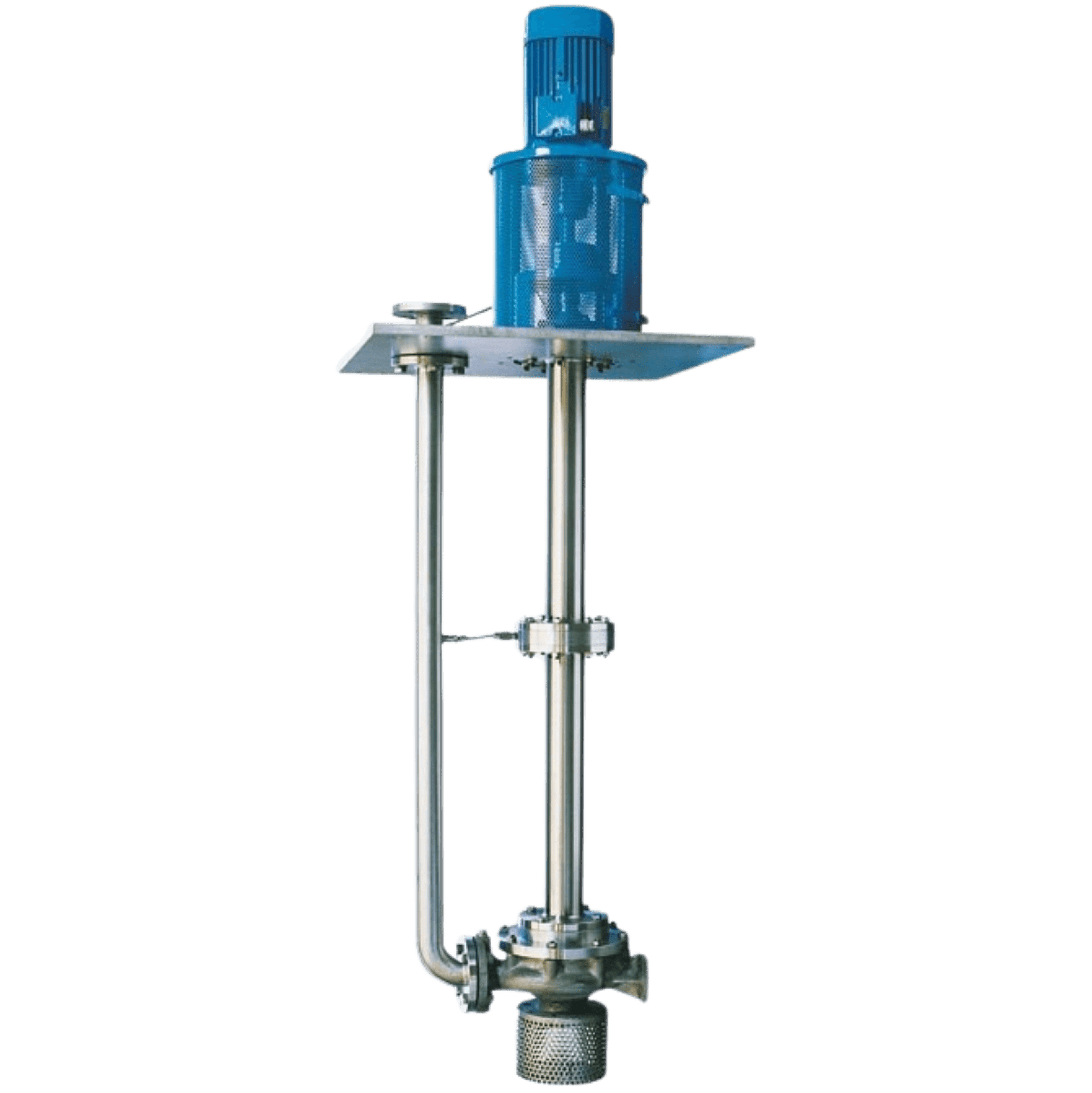
Vertical sump pump vibration is almost never a hydraulic problem. The duty point is met, the curve is honoured, the witness test passes on the shop floor — and six weeks after commissioning the shaft is grooved, the bushings are wiped, and the seal is weeping. The reason is that a vertically suspended pump is the one machine in a plant where the mechanical design is set by a dimension nobody negotiates carefully: the distance from the sump plate to the impeller. Column length decides the shaft's first lateral critical speed and it decides the structure's reed critical frequency, and both of those are properties of the installation, not of the pump on the catalogue page. Getting this wrong is expensive because the failure mode is progressive and looks like something else — it presents as a bearing problem, a balance problem, or an alignment problem, and each of those gets fixed in turn while the resonance that caused all three stays exactly where it was.
The rotor is hanging, not resting
Start with the structural difference. In a horizontal end-suction pump the rotor sits in its bearings under its own weight. Gravity acts perpendicular to the shaft axis, so every journal carries a steady, predictable radial load, and that load is what a hydrodynamic film needs in order to form. The rotor is gravity-stabilised before it ever turns.
A vertically suspended pump has no such stabilising load. As Hydro Inc's Dr T Ravisundar puts it in a review of vertical pump repair practice, the vertical rotor is suspended from the top and is not gravity-stabilised; the gyroscopic effect of rotation can do considerable damage to rotor and casing once anything goes wrong. Gravity now acts along the shaft axis, where it is carried by the thrust bearing at the top and contributes nothing to the radial stability of the intermediate bearings. The line shaft is, mechanically, a long slender beam held at one end and guided — loosely — at intervals along its length.
Everything that follows is a consequence of that. The intermediate bearings are not carrying load; they are setting stiffness. And stiffness is what determines where the critical speeds land.
What actually sets the first lateral critical speed
The first lateral critical speed of a line shaft is governed by the shaft's own bending stiffness and by the stiffness of the bearings supporting it. Shaft stiffness in bending scales with the fourth power of diameter and falls off with the cube of unsupported span, so the span between supports is the dominant lever. Double the free length between two bearings and you do not lose a little margin — you lose most of it.
Bearing spacing is the design variable, not a detail
This is why bearing spacing is a hydraulic-institute-level concern rather than a shop preference. Hydro Inc's guidance is blunt: if the spacing of line shaft bearings is larger than recommended, a natural frequency on the shaft can develop within the operating range, permitting damaging vibration and premature failure. The intermediate bearings exist primarily to break the shaft into spans short enough that the first critical speed stays clear of running speed. Their load-carrying duty is secondary.
A documented case makes the scale of it concrete. Malcolm Leader and colleagues analysed six new vertical sulfur pit pumps that showed unacceptable vibration immediately on commissioning. The line shaft was 144 inches long and 2.5 inches in diameter, with the two controlling centre bushings spaced 48.75 inches apart. Running speed was 3,575 rpm. With the original plain bushings, the calculated first lateral critical speed was 1,770 cpm — almost exactly half running speed. Measured subsynchronous vibration on top of the motor reached 1.5 inches per second, with the synchronous 1x component effectively absent from the spectrum. The pump was not unbalanced. It was resonant, and it was unstable.
Why plain bushings go unstable when there is no load
The second half of that case explains a failure mode that catches people who reason from horizontal-pump experience. In a vertical orientation there is very little radial load between shaft and bushing. Leader's analysis states the consequence directly: in that condition virtually all plain cylindrical bushings are inherently unstable, because they cannot generate a hydrodynamic pressure field strong enough to hold the journal at a stable equilibrium point. The journal orbits instead of sitting. What you measure is a forward whirl at slightly under half running speed — the same signature as classic oil whirl, here driven by the process liquid that is doing the lubricating.
The fix in that case was not structural and not a rebalance. Replacing the two centre bushings with a three-lobe profile raised principal stiffness from 1,830 lb/in to 49,100 lb/in — roughly a twenty-seven-fold increase — and cut the destabilising cross-coupled stiffness to about 30 percent of its original value. That stiffness increase lifted the first critical speed clear of the half-speed excitation, the unstable whirl mode ceased to exist, and field measurements after installation confirmed the subsynchronous component was gone. No structural bracing was required.
A long vertical shaft does not fail because it is long. It fails because the length moved a frequency into the operating range and nobody checked.
The structure has its own natural frequency, and it is usually the one that bites
Below the sump plate you have rotor dynamics. Above it you have a separate problem: a heavy motor cantilevered on a relatively flexible discharge head. The first above-ground natural frequency of that assembly is the reed critical frequency, and National Pump Company describes it as the single greatest factor in preventing excessive vibration in a vertically suspended pump.
The Level 1 calculation in ANSI/HI 9.6.8 treats the arrangement as a cantilever spring supporting a mass: the discharge head is the spring, the motor is the mass, and the motor manufacturer supplies the centre-of-gravity location, deflection at the centre of gravity, unit weight and motor reed critical frequency as inputs. Second-mode frequencies are estimated at roughly four times the first. It is a handbook calculation and it is fast, which is precisely why there is no excuse for skipping it.
ANSI/HI 9.6.8, the Hydraulic Institute's Guideline for Dynamics of Pumping Machinery, sets out three analysis levels: Level 1 simple closed-form calculation, Level 2 intermediate mass-elastic or finite element modelling, and Level 3 advanced multi-program analysis including foundation flexibility and forced response. Reed critical frequency is addressed in section 9.6.8.5.7 and Appendix C, with motor reed frequency data in Appendix D and sample specification wording for separation margin in Appendix E. The guideline exists so that a specifying engineer can put a number in a tender document rather than hoping the vendor thought about it.
Separation margin, and why constant speed is not a free pass
Resonance is not a binary. Amplification rises as excitation approaches a natural frequency, so the question is how much clearance you demand. Hydraulic Institute guidance holds that there generally needs to be a minimum of 10 percent separation between a forcing frequency and a natural frequency unless there is enough damping to limit the amplification. That 10 percent is a field acceptance figure. Analysis margins are deliberately wider to absorb modelling and data uncertainty: National Pump Company recommends no less than ±25 percent for a Level 1 analysis and no less than ±20 percent for a Level 2 finite element analysis.
Two forcing frequencies matter. Running speed itself is the obvious one. Vane pass frequency — running speed multiplied by the number of impeller vanes — is the one people forget, and on a 2900 rpm machine it lands high enough to excite second-mode structural behaviour.
Variable speed changes the problem entirely. A constant-speed pump has a single excitation frequency to avoid. A VFD-driven pump sweeps a band — typically 70 to 100 percent of full-load speed in practice — and every natural frequency inside that band will be passed through on every ramp. If a resonance cannot be designed out, the remaining options are a fabricated discharge head engineered specifically for the speed range, or a programmed lockout band in the drive. Both are far cheaper decided at tender than discovered at commissioning.
What to check before you release the order
For a vertical sump pump, the datasheet questions that predict service life are mostly not hydraulic ones. Work through these:
- Shaft length and speed together, never separately. A 5 m column at 1450 rpm and the same column at 2900 rpm are different machines dynamically; ask which speed the dynamic analysis was performed at.
- Intermediate bearing spacing, stated as a dimension. If the vendor cannot tell you the unsupported span, no critical speed calculation has been done.
- First lateral critical speed of the line shaft, with the separation margin to running speed stated as a percentage.
- Reed critical frequency of the pump-and-motor structure, and whether it came from a Level 1 calculation or a Level 2 finite element model — the acceptable margin differs between them.
- Motor reed critical frequency data from the motor supplier. A Level 1 RCF calculation is not possible without it, so its absence tells you the calculation was skipped.
- Bushing geometry and material against the actual pumped liquid, including its temperature-dependent viscosity. A liquid that thins or thickens sharply with temperature changes the film the bushing depends on.
- The dry-running exposure the installation will impose: how many starts per hour, and how long the bushings run without liquid on each one.
- Whether the operating speed range is fixed or driven by a VFD, and if driven, what happens in the band between minimum and maximum speed.
Lubrication, materials, and the failure you will actually see
Line shaft bearings are lubricated one of two ways. An open line shaft is product-lubricated — the pumped liquid is the lubricant. An enclosed line shaft runs inside an enclosing tube and is flushed with clean water, oil-lubricated by gravity or pressure feed, or grease-packed. The choice is not a preference; it follows from whether the process liquid is fit to be a lubricant.
Frequently it is not. Hydro Inc documents a set of four service-water pumps that were achieving only six to twelve months between repairs. Root cause analysis found two contributors: river water too dirty to flush the line shaft bearings, and poor inlet conditions restricting suction flow. The remedy was an enclosing tube fed from an external clean water source, a bearing material change to bronze, and a strainer basket at the suction bell. Two years later the pump was still in service. The point is that the bearing material was only one of the three changes, and on its own it would not have been enough.
Material selection spans metallic options such as bronze, cast iron and Nitronic stainless, carbon with various fillers, rubber, and composites including glass-filled epoxy and PTFE. Temperature, abrasiveness, lubricity and corrosivity all pull in different directions, and the correct answer changes with the liquid rather than with the pump model.
One more constraint is geometric rather than dynamic. The governing repair and assembly principle for vertical pumps is that the maximum relative radial displacement between stator and rotor, at any point along the full length of the machine, must stay below the minimum clearance of the closest running fit. On a 5 m column that is a demanding tolerance stack, and it is the reason vertical pumps reward tight manufacturing discipline far more than horizontal ones do.
Where this lands in specification practice
Dimensional standards help, but they do not solve this. ISO 2858, prepared by ISO/TC 115, specifies principal dimensions and the nominal duty point for end-suction centrifugal pumps rated to 16 bar. That standardisation buys interchangeability and predictable envelopes — genuinely useful when a pump has to be replaced in an existing pit. What it does not do is tell you anything about the dynamics of the specific column length you are installing, because that dimension is yours, not the standard's.
AIRFIN's VCP Series vertical long shaft sump pump is designed to DIN 24256 (ISO 2858) and is offered with shaft lengths up to 5 metres, sizes from 25 to 125 mm, capacities to 325 m³/hr and heads to 60 m, at either 1450 or 2900 rpm, in materials from cast iron through SS 304 and SS 316 to Alloy 20, bronze and C4DMCU duplex, for service up to 80 °C. Two features of that arrangement bear directly on everything above. The motor is mounted above the sump plate rather than submerged, which puts the driver mass at the top of a cantilever and makes the reed critical frequency of the head-and-motor assembly a design item rather than an afterthought. And the availability of both 1450 and 2900 rpm configurations means the same hydraulic duty can often be met at the lower speed, which is the single most effective way to open up separation margin on a long column.
The judgement to carry away is this. When you specify a vertical sump pump, you are not buying a pump — you are buying a pump plus a column length that you chose, and the column length is the variable that decides whether the machine runs for a decade or is pulled in nine months. Ask for the critical speed, the reed critical frequency, and the separation margins as stated numbers before the order goes out, and ask whether the same duty can be met at 1450 rpm instead of 2900. Both questions cost nothing at tender stage and cannot be answered cheaply afterwards. AIRFIN manufactures the VCP Series in-house, with performance testing and material certification carried out in its own facility, and can advise on shaft configuration, bearing arrangement and material selection for a specific sump depth and liquid.