
Why NPSH Margin, Not NPSHR, Decides Pump Reliability
How NPSH margin, suction lift, and flow rate decide whether a self-priming pump cavitates in service, and how to size it.
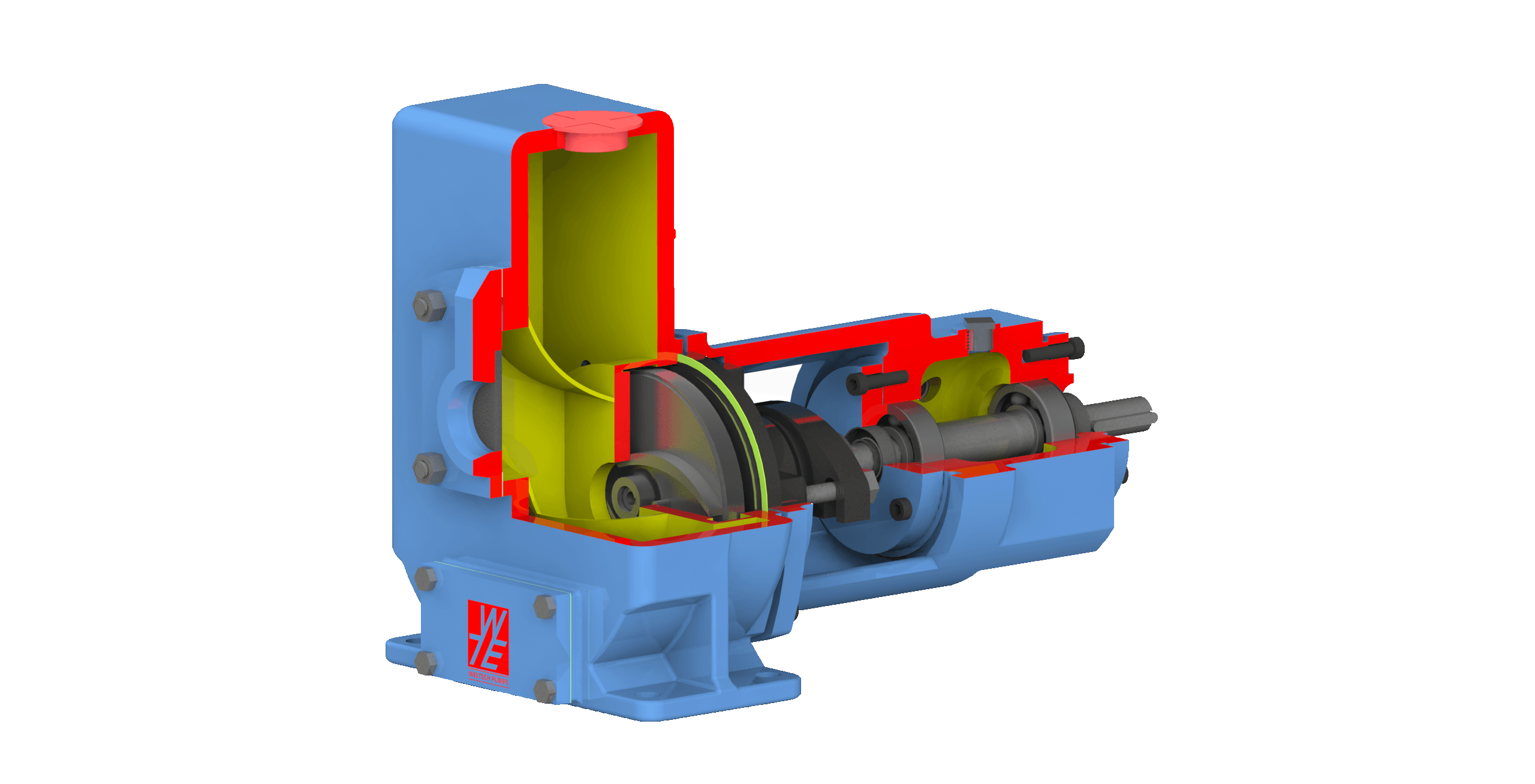
A self-priming pump that fails in service rarely fails on the discharge side. It fails because somebody read the NPSHR figure off a datasheet, confirmed that the calculated NPSH available exceeded it, and closed the selection. NPSH margin — the gap between what the system can deliver at the pump suction and what the pump actually needs there — is the most consistently under-specified number in wastewater pumping. Getting it wrong does not produce a dramatic failure on commissioning day. It produces an impeller that erodes quietly, a mechanical seal that fails at eighteen months instead of five years, and a duty point that has drifted below the curve you were promised without anyone noticing.
What NPSH Actually Measures
NPSH is expressed as head rather than pressure because head is fluid-independent: a pump will lift different liquids to the same height regardless of their density. NPSH available is the total head at a point in the system, measured in metres or feet absolute, in excess of the vapour pressure of the liquid at its operating temperature. It is a measure of how close the liquid is to flashing.
The Hydraulic Institute illustrates this with a static tank. At sea level, standard atmospheric pressure is 14.7 psi absolute, and one psi corresponds to 2.31 feet of water at 68 °F with a specific gravity of 1.0. A tank holding 23 feet of water reads 10 psig at the base, which is 24.7 psia, or roughly 57 feet absolute. Subtract the 0.34 psia vapour pressure of the water — about 0.78 feet — and the NPSH available at that point is 56.2 feet. To vaporise the water there, you would have to remove all 56.2 feet of that margin.
The reason this matters at the pump rather than at the tank is what happens inside the impeller. As liquid enters, there is a region of reduced head at the impeller eye before the impeller imparts any energy to it. Pressure is at its minimum there. If it falls below the vapour pressure of the liquid, vapour forms. Those bubbles are then carried into a higher-pressure region of the impeller where they collapse. Two things follow: the vapour blocks flow area and degrades hydraulic performance, and the repeated collapse erodes metal. That is cavitation, and it originates on the suction side even though the damage often shows up elsewhere in the machine.
NPSHR Is a Damage Point, Not a Safety Threshold
The most costly misreading in pump selection is treating the published NPSHR curve as the line below which cavitation starts. It is not. NPSHR is defined by a test convention that the Hydraulic Institute adopted in 1932: hold flow constant, progressively reduce suction head, and record the NPSH at which total head falls by three percent. Three percent was chosen because it was the smallest head drop that could be consistently and practically measured, not because it represents a safe operating condition. Manufacturers still plot this value, often labelled NPSH3 or NPSH3%, against flow rate. Tests are normally run on water at 20 °C, and for multistage pumps only the first stage is considered in determining the three percent drop.
By the time NPSH available equals the published NPSHR, the pump is already cavitating and already three percent down on head. NPSHR marks where the damage becomes measurable, not where it begins.
The Hydraulic Institute is explicit that the full published head will not be achieved when NPSH available equals NPSH3. The 1932 consensus was that pumps run at three percent head drop would still give acceptable service life, and for the larger, slower machines of that era it probably was. Today's higher-speed, higher energy-density pumps may not achieve acceptable service life under those suction conditions without meaningful margin above NPSH3, which is why ANSI/HI 9.6.1 exists as a separate guideline on margin rather than being folded into the pump curve.
Some manufacturers publish a second figure, sometimes called NPSH40,000, set above the standard NPSHR. Where NPSH available exceeds it, the intent is a guarantee of no performance loss or parts replacement across roughly 40,000 hours — about four and a half years of continuous running. The existence of that second number is itself the clearest admission that the first one is not a reliability threshold.
NPSH Available Is a System Property, and It Shrinks
NPSH available is calculated from the suction-side configuration: absolute pressure at the liquid surface, minus vapour pressure, plus or minus the static elevation between the liquid surface and the impeller centreline, minus friction losses through the suction pipework, plus velocity head at the pump flange. Every one of those terms is a design assumption, and several of them move after handover.
The terms that drift after commissioning
Atmospheric pressure sets the ceiling. At sea level the theoretical maximum suction lift for cold water is about 10.3 metres, and available lift falls by roughly one metre for every 1,000 metres of altitude. A selection validated for a coastal site does not transfer unchanged to an inland plant on a plateau.
Temperature moves vapour pressure, and vapour pressure is subtracted directly. Warmer liquid means less available margin, which is why a pump comfortable on cold water at a given lift can struggle on warm effluent at a shorter one. Industrial streams that arrive warm from process, or open channels that heat through a summer afternoon, erode the margin that was calculated on a cool day.
Friction loss is the term that degrades. Suction strainers foul, pipe internals scale and roughen, and at some point in the plant's life somebody adds an isolation valve or a bend that was not in the original hydraulic calculation. Because friction loss scales with the square of velocity, the penalty is not linear. In practice, friction, vapour pressure, and the pump's own NPSH requirement reduce the usable suction lift for clean cold water at low altitude to somewhere around seven to eight metres, well short of the theoretical figure.
Why NPSHR Climbs Steeply With Flow
Impellers are designed for one flow rate at which the approaching liquid meets the inlet vane tips at zero incidence angle — shockless entry. That flow sits close to the best efficiency point. Move away from it in either direction and the incidence angle grows, which promotes flow separation at the vane inlet and localised cavitation. The Hydraulic Institute defines a preferred operating region either side of BEP within which efficiency and reliability are not substantially degraded, and a wider allowable operating region beyond it where service life remains acceptable but flow through the pump is no longer uniform.
The consequence for suction design is that NPSHR is not a single number. It rises with flow, and the rise accelerates past BEP, following a roughly second-order relationship in the upper flow range. NPSH available moves the opposite way over the same range, because suction friction losses increase with the square of velocity. The two curves converge from both directions at once, which is why a pump selected with apparently comfortable margin at design flow can be cavitating at end-of-curve.
AIRFIN's SM/SG series performance data shows this plainly. On the SM/SG 65-120 model, NPSHR is 0.9 m at 9 m³/hr, 1.9 m at 24 m³/hr, 2.7 m at 30 m³/hr, and 9.2 m at 45 m³/hr. The suction requirement multiplies roughly tenfold across the curve while the flow rises fivefold. On the SM/SG 65-160, the same pattern runs from 2.5 m at 9 m³/hr to 7.0 m at 36 m³/hr. A selection made at the left of that curve tells you almost nothing about the suction conditions the pump will face if the duty point migrates right — which is exactly what happens when a system is oversized and the pump runs out along its curve against lower-than-designed system resistance.
This is also why margin cannot be a fixed number applied everywhere. The Hydraulic Institute's guidance is that required NPSH margin increases at flows beyond the preferred operating region. Operating region and NPSH margin are one problem, not two.
Why Self-Priming Pumps Live Closest to the Edge
A self-priming centrifugal pump is specified precisely when the liquid sits below the pump — an underground sump, a wet well, a flooded excavation. That is the one configuration in which the static elevation term in NPSH available is negative rather than positive. Self-priming pumps therefore start with less margin than any other centrifugal arrangement, by definition of the duty they are chosen for.
The priming mechanism deserves understanding, because its failure modes look like cavitation and are often misdiagnosed as such. A conventional centrifugal pump cannot evacuate air; with no seal between suction and discharge it simply becomes air-bound. A self-priming design surrounds the impeller and volute with a reservoir. On start-up the pump behaves as a liquid-ring pump: the impeller throws the retained charge into a cylindrical ring against the casing wall, which forms a gas-tight seal preventing air returning from discharge to suction. Air drawn from the suction line is trapped between the impeller vanes, carried to the discharge port, expelled, and the liquid falls back into the reservoir under gravity. Liquid climbs the suction line until it displaces all the air, at which point normal pumping begins.
That mechanism imposes its own constraints. The charge must be present — a self-priming pump is not a dry-running pump. Suction pipework volume should be minimised, because a long prime risks evaporating the charge before liquid arrives. The suction line must be genuinely airtight; a leak means the pressure never falls far enough to lift liquid at all. And because the liquid ring depends on tight impeller-to-casing clearance, anything that degrades that clearance degrades priming: debris lodged in the recirculation port, solids collecting on the impeller, ordinary wear opening the gap over years, or incorrect reassembly after maintenance. On sewage and sludge duty, all four are live risks rather than theoretical ones. AIRFIN's SM/SG series is built for that reality with a non-clog hydraulic passing up to 20 mm solids on the 65-120 and 24 mm on the 80-140, with semi-open and closed impeller options, to ISO 2858.
A Selection Checklist for Suction-Limited Duty
When the pump sits above the liquid, work the suction side before the discharge side. The following checks catch most of the failures that show up in the first two years of operation:
- Calculate NPSH available at the highest flow the pump can reach against the lowest credible system resistance — not at the nameplate duty point.
- Read NPSHR at that same end-of-curve flow, not at BEP. On the SM/SG 65-120 the difference between those two readings is over eight metres of head.
- Use the lowest liquid level and the warmest liquid temperature the plant will see, not annual averages.
- Add the site's altitude correction — roughly one metre of lift for every 1,000 metres of elevation.
- Include fouled-condition friction losses for strainers and suction pipework, not clean-pipe values.
- Confirm the duty point falls inside the preferred operating region; if it does not, increase the margin rather than accepting the catalogue figure.
- Check that the suction line is airtight, free of high points that trap air, and as short and direct as the layout permits.
- For solids-bearing streams, verify the maximum permissible solid size against the actual screening upstream, and specify a cutter or agitator variant where fibrous material is expected.
How Much Margin Is Enough
As a working minimum, NPSH available should exceed NPSHR by at least 0.5 metres, with 0.5 to 1.0 metres commonly applied to account for weather-driven variation in temperature and atmospheric pressure and for friction losses that grow over the system's life. Margin is expressed either as a difference in head or as a ratio; for higher-energy pumps where NPSHR is large, the ratio is the more meaningful form.
ANSI/HI 9.6.1 gives application-specific values, and the convention is to apply whichever of the ratio or the absolute figure is greater. For typical water service with a stainless steel or aluminium-bronze impeller below 75 kW per stage, the guideline gives a 1.1 ratio or a 1.5 metre minimum. For a general catalogue pump the figure is a 1.1 ratio or 1.0 metre. For chemical process duty it runs from a 1.1 to 1.2 ratio, or 0.6 to 1.0 metres. These are floors for well-behaved applications, not allowances for a pump running hard right of its preferred region on warm effluent through a fouling strainer.
It is worth recalculating margin whenever capacity changes. Because NPSHR rises with flow while NPSH available falls, a capacity uprate that looks trivial on the discharge side can consume the entire suction margin. The same applies to a change in liquid temperature, a new upstream process that raises effluent temperature, or a relocation of the pump relative to the sump.
The practical judgement to carry away is this: NPSHR is a test result, not a specification limit, and NPSH available is a calculation that decays from the day the plant is commissioned. Design the suction side for the worst combination the plant will actually see — lowest level, warmest liquid, fouled strainer, highest flow the pump can reach — and hold real margin above the published curve at that point. A pump selected this way will run quietly for years on a duty that destroys a pump selected on the datasheet number alone. AIRFIN manufactures the SM/SG self-priming series in-house and can advise on suction-side selection or retrofit for existing installations where prime loss or cavitation has become a recurring problem.